
A Language Workbench in Action - MPS
Using a language workbench is very different to working with traditional Domain Specific Languages. This is an example of building a small but interesting DSL using the JetBrains Meta Programming System (MPS). You can use this to get a feel of what working with language workbenches would be like.
12 June 2005

(If you aren't familiar with language oriented programming and language workbenches - or at least my usage of the terms, you should read my outline article on Language Workbenches. This article discusses an example of using a language workbench and assumes you'll be familiar with the concepts I discussed in that article.)
One of these language workbenches is the Meta-Programming System (MPS) from JetBrains. As I was writing my language workbench article I wanted to include a more substantial example with in an actual language workbench to help give you a better picture of what working with such a tool would be like. The example ended up being a big one to describe, so I decided to break it out into its own article.
I decided use MPS not because of any opinions about which language workbench is the best (after all they are still in very early stages of development), but simply because that the JetBrains office is just down the road from where I live. A short distance to drive makes collaboration much easier. So as you read this, remember that only part of the point is to look at MPS. The real point of the article is to give you a feel of what this class of tools is like to use. On the surface each tool is quite different - but they share many underlying concepts.
JetBrains have opened up the MPS in their Early Access Program, which allows people to download a development version of MPS to play with it. You'll find the example from this article in there. Remember, however, that the tool is still very much under development so what you see when you look at it now may be very different from what I see as I write this. In particular certain screens may have changed and I don't expect to keep the screenshots here up to date with each change. There are also numerous rough edges which are typical of a new kind of tool that still being worked on. However I think it's still worth looking at because the principles are what counts.
Agreement DSL
This example uses a pattern that I've come across several times, which I now call Agreement Dispatcher. The idea behind an agreement dispatcher is that a system receives events from the outside world and reacts to them differently due to various factors, of which a leading one is the agreement between the host company and the party that the event was about.
Perhaps the easiest way to talk about this further is to show an example of the DSL I'll be using as an example.
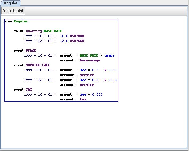
Figure 1: Agreement DSL for a regular plan.
This piece of DSL indicates how a notional utility company reacts to events for customers on its regular plan. The agreement definition consists of values and event handlers, both of which are temporal - their values change over time.
This agreement has one value - the base rate that the customer is charged for electricity. From 1 Oct 1999 it was set at $10 per KwH, on the 1st December it was raised precipitously for $12/KwH.
The agreement shows reactions to three kinds of events: usage (of electricity), a service call (such as someone coming in to fix a meter), and tax. The handlers are temporal in the same way as the base rate; we can see that the handler for service calls also changed on December 1st.
The handler indicates a simple reaction - the posting of some monetary value to an account. The account is stated directly in the DSL, the amount is calculated using a formula. The formula can include values defined in the agreement together with properties on the event. Usage events include a usage property that indicates how many KwH of electricity were used in this billing period. The posting rule for the USAGE event indicates than when we get a usage event we post the product of this usage and the base rate to the customer's base usage account.
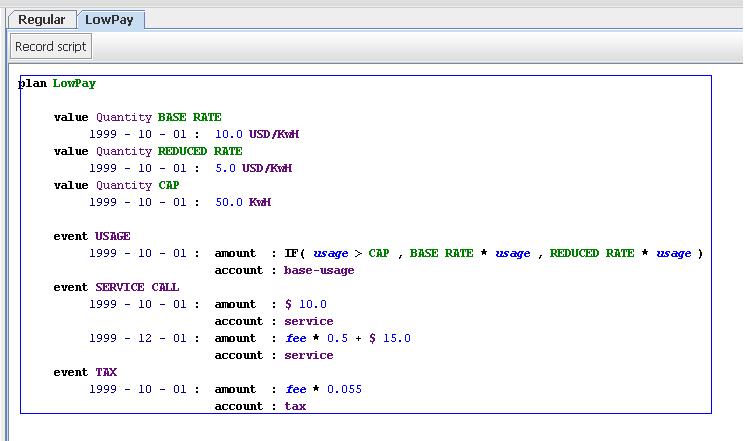
Figure 2: Another DSL fragment for low pay cases.
Figure 2 shows a second agreement, this one for low paid people on a special plan. The only interesting addition to this is that usage formula here involves a conditional, expressed using Excel syntax.
The first thing to note about these fragments is that they are very domain oriented and readable in terms of the domain. Although the COBOL inference hangs over me, I'd venture to say they are readable to a non-programmer domain expert.
These DSL fragments will generate code that fits into a framework written in Java, indeed these DSLs describe the same scenarios that I used in the description of agreement dispatcher.
For the sake of comparison, here's the same configuration code written in Java.
public class AgreementRegistryBuilder {

    public void setUp(AgreementRegistry registry) {
        registry.register("lowPay", setUpLowPay());
        registry.register("regular", setUpRegular());
    }

    public ServiceAgreement setUpLowPay() {
        ServiceAgreement result = new ServiceAgreement();
        result.registerValue("BASE_RATE");
        result.setValue("BASE_RATE", 10.0, MfDate.PAST);
        result.registerValue("CAP");
        result.setValue("CAP", new Quantity(50, Unit.KWH), MfDate.PAST);
        result.setValue("CAP", new Quantity(60, Unit.KWH), new MfDate(1999, 12, 1));
        result.registerValue("REDUCED_RATE");
        result.setValue("REDUCED_RATE", 5.0, MfDate.PAST);
        result.addPostingRule(EventType.USAGE,
                new PoorCapPR(AccountType.BASE_USAGE, true),
                new MfDate(1999, 10, 1));
        result.addPostingRule(EventType.SERVICE_CALL,
                new AmountFormulaPR(0, Money.dollars(10), AccountType.SERVICE, true),
                new MfDate(1999, 10, 1));
        result.addPostingRule(EventType.TAX,
                new AmountFormulaPR(0.055, Money.dollars(0), AccountType.TAX, false),
                new MfDate(1999, 10, 1));
        return result;
    }
    public ServiceAgreement setUpRegular() {
        ServiceAgreement result = new ServiceAgreement();
        result.registerValue("BASE_RATE");
        result.setValue("BASE_RATE", 10.0, MfDate.PAST);
        result.setValue("BASE_RATE", 12.0, new MfDate(1999, 12, 1));
        result.addPostingRule(EventType.USAGE,
                new MultiplyByRatePR(AccountType.BASE_USAGE, true),
                new MfDate(1999, 10, 1));
        result.addPostingRule(EventType.SERVICE_CALL,
                new AmountFormulaPR(0.5, Money.dollars(10), AccountType.SERVICE, true),
                new MfDate(1999, 10, 1));
        result.addPostingRule(EventType.SERVICE_CALL,
                new AmountFormulaPR(0.5, Money.dollars(15), AccountType.SERVICE, true),
                new MfDate(1999, 12, 1));
        result.addPostingRule(EventType.TAX,
                new AmountFormulaPR(0.055, Money.dollars(0), AccountType.TAX, false),
                new MfDate(1999, 10, 1));
        return result;
    }

}
The configuration code isn't exactly the same. The posting rule carries a taxable boolean marker that we haven't added to the DSL yet. In addition the formulae are replaced by various Java classes that can be parameterized for the most common cases - this if often better than trying to dynamically create formulae in a Java solution. But I think the basic message comes across - it's much harder to see the domain logic in the Java, because Java's grammar does get in the way. This is particularly so for a non-programmer.
(If you're interested in how the resulting framework actually works, take a look at the agreement dispatcher pattern - I'm not going to go into it here. The example in that pattern is similar, but not exactly the same.)
You may have noticed that the DSL examples used screen shots rather than text - and that's because although the DSLs look like text they aren't really text. Instead they are projections of the underlying abstract representation, projections that we manipulate in the editor.
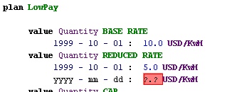
Figure 3: Adding a new rate
Figure 3 indicates this. Here I'm adding new base rate. The editor indicates the fields I need to fill in, putting in appropriate values as required. I don't actually type much text - often my main task is picking from pick lists. At the moment the date goes in as structured figures, but in a fully developed system you could use a calendar widget to enter the date.
One of the most interesting elements of this is the use of excel-style formulae in the plan. Here's the editor as I add a term to a formula.
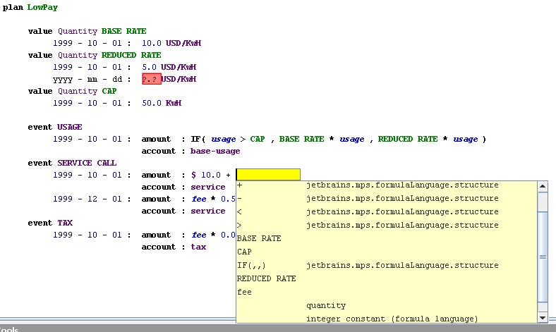
Figure 4: Editing a formula.
Notice that the pop up includes various expressions you might want in a formula, plus the values defined in the plan, plus the properties on the event that's being handled in this context. The editor is using a lot of knowledge of the context to help the programmer enter code correctly - much as post-IntelliJ IDEs do.
Another point about the formulae is that they come from a separate language from the language used to define agreements. So any DSL that needs to use excel-like formulae can import formulae to their language without having to create all the definitions for themselves. Furthermore these formulae can incorporate symbols from the language that's using the formula language. This is a good example of the kind of symbolic integration that language workbenches strive for. You need to be able to take languages defined by others, but at the same time weave them as seamlessly as possible into your own languages.
(As a point of full disclosure, this formula language was in fact written in response to developing this example, but it is separated so it can be used by other languages. This is an accident of the fact we are seeing a tool in development, together with MPSs development philosophy: find interesting applications of MPS and use the needs of these applications to drive the features and design of MPS. This is a development philosophy I favor.)
That last screen-shot shows another important point. You'll notice that I didn't finish working on the new rate when I switched over to the formula. One of the past problems with these kind of intelligent, or structured, editors is that they couldn't deal with incorrect input. Each bit of input needs to be correct before you move on. Such a requirement is a big usability problem. When programming you need to be able to switch around easily - even if that means leaving invalid information in place. The consequence of this, for a projecting editor, is that you need to be able to handle invalid information in your abstract representation. Indeed you want to be able to do this and still be able to function as much as possible. In this case one option would be to generate code from the plan, ignoring those temporal elements that are in error. This kind of robust behavior in the face of wanton invalidity is an important feature of language workbenches.
The example in MPS here uses a text-like projection. MPS, thus far, focuses on this kind of projection. In contrast the Microsoft DSL tools focus on a graphical projection. I expect that as tools develop they will offer both textual and graphical projections. Despite the modeling crowd's obsession with saying “a picture is worth a thousand words”, textual representations are still very useful. I would expect mature language workbenches to support both textual and graphical projections - together with projections that many people don't think as programming environments
Defining the Schema
Now we can see what the language looks like, we can take a look at how we define it. I'm not going to go through the entire language definition here, I'm just going to pick out a few highlights to give you a feel how it works.
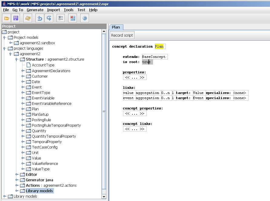
Figure 5: The schema for Plan
Figure 5 shows the schema for the plan construct. (I've also shown on the left the list for other concepts in this agreement language.) If you've done any data modeling, or in particular meta-modeling, this shouldn't have any surprises. I'm not going to explain all elements of the definition here - only the highlights. As usual, remember that this is currently in flux, it probably doesn't look quite like this any more.
We define a concept, allow it to extend (inherit from) other concepts. We can give our concept properties and links (similar to attributes and relationships) both at the instance and concept (class level). With links we indicate the multiplicity (in both directions), and the target concept.
So in this case we see that a plan is made up of multiple values and events, each of which have their own definitions. Figure 6 shows the definition for event, which is pretty simple.
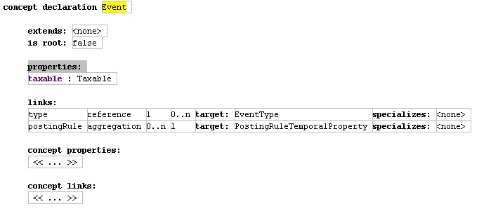
Figure 6: Schema for Event
We get something new in the posting rule temporal property. Both values and posting rules end up being governed by this kind of temporal rule, so it makes sense to factor out the common ability to have date-keyed logic. So we have both a temporal property definition (Figure 7) and extend that with a temporal property for posting rules (Figure 8).
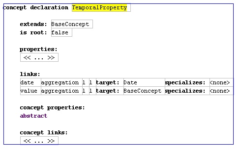
Figure 7: Schema for temporal property
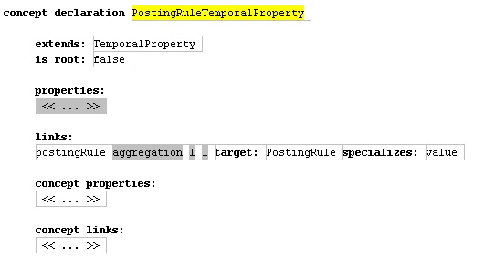
Figure 8: Schema for the temporal link to posting rules.
In this case the temporal property defines the notion of a validity date and a value. The posting rule temporal property extends this - but does so in a way that's slightly different to inheritance in an object-oriented language. Rather than adding new link, it specializes this value link saying that it can only link to posting rules. This is similar to what you would achieve with generics in programming language. This idea of specializing a relationship is present in several modeling languages (including UML). I didn't find it terribly useful for most modeling but it is rather handy for meta-modeling. You can think of it as a particular form of constraint.
Finally I'll show how the posting rule itself is defined.
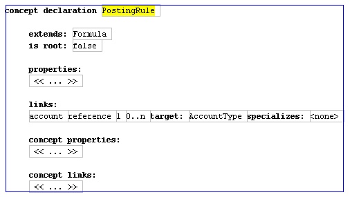
Figure 9: Schema for posting rule.
It extends a concept called formula, which is actually part of a separate formula language.
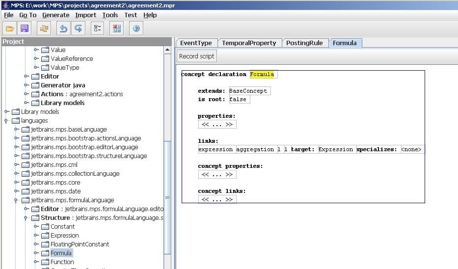
Figure 10: Schema for formula from a separate language.
So from this you can get a sense of what's involved to set up a schema in MPS. For each concept you edit the definition making the various links between the elements. I suspect that a data model or UML like class diagram would work better here - this is the kind of thing that works nicely in diagrammatic form. However this style of editor also works pretty well and can allow you to enter a new language schema fairly rapidly.
If you're thinking what I hope you're thinking, you'll have noticed something else. The screens for editing schemas look awfully like the screens for editing the DSL. As you may guess there is a DSL for editing schemas - called the structure language in MPS. I edit the schema using the editor that's part of the that DSL. This kind of metacircular bootstrapping is common in language workbenches.
Building Editors
Now lets take a look at how we define editors in MPS.
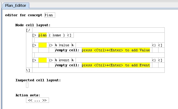
Figure 11: The editor definition for plans.
Figure 11 shows the editor for a plan. In general we build an editor for each concept in our model. (It's not quite one for one, but that's a good place to start thinking.)To define the editor for plans we use the editor for editors (it's getting hard to avoid the metacircularity here.) Editors are defined as a hierarchy of cells. The leaves of the hierarchy can be constants, or references to elements in the the schema. The editor editor (which we are looking at now) uses some symbols to help delimit parts of the editor. Although these symbols are a bit cryptic it's important not to get worried about notation with language workbenches since notation is very easy to change.
The top of this cell hierarchy is a cell collection for the whole editor. I select this by selecting the '[/' cell.
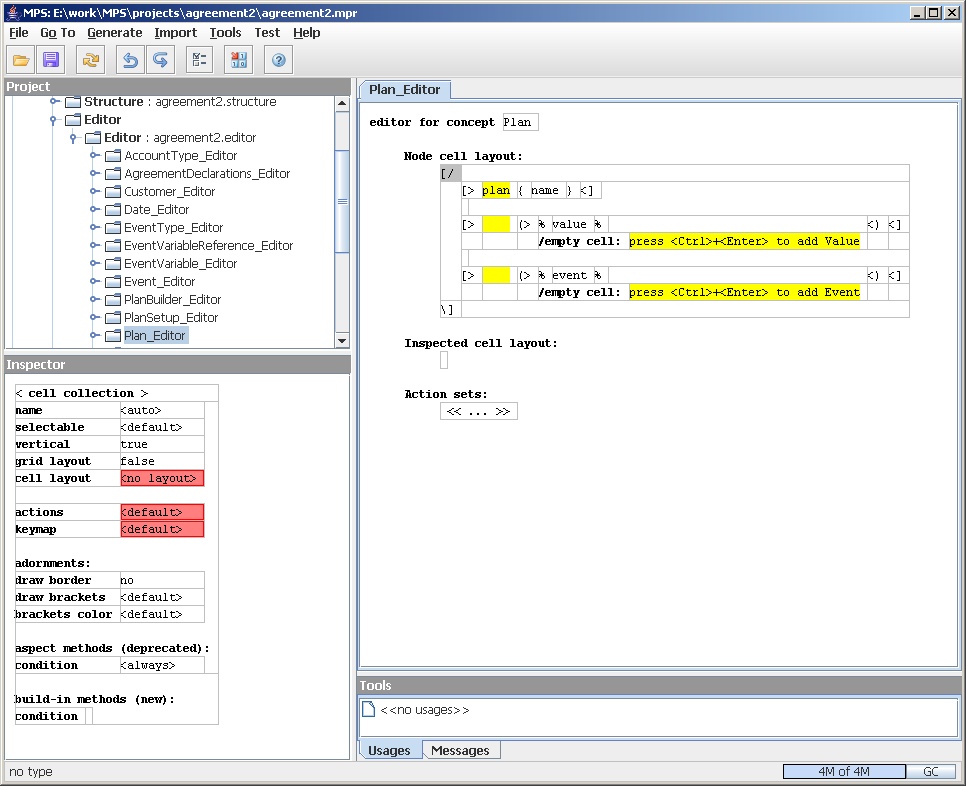
Figure 12: Selecting the top of the cell hierarchy.
When you're working with the editor editor, the inspector frame (bottom left) which we didn't use earlier now becomes important. The inspector is used in the same way that property editors are used in GUI builders. Here the inspector shows that we have a vertical cell collection. The sub-cells are:
- The row beginning
[> plan - A blank row
- The row including
% value %and its following row. - Another blank row
- The row including
% event %and its following row.
As you can see, one of the problems with this projection is that it's hard to figure out the actual cell hierarchy. It's also questionable to use blank cells to show indentation and whitespace. I expect there'll be a good bit more work on how to make editor editors more usable in the future.
The three non-blank rows correspond the line naming the plan, the lines of values, and the lines of events in the plan editor.
Figure 1: Here's the example for regular plans again. See how the three non-blank lines in the plan editor correspond to three content areas in the plan: name, values, and events.
Now I'll dig into the first of these content areas, the name of the plan. It helps that this is the simplest area to dig into, but even so it's hard to describe it in an article like this because the editor editor uses the inspector to provide a lot of information - as a result I need to use a lot of screen-shots.
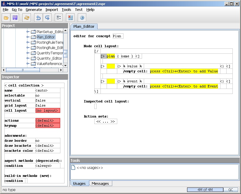
Figure 14: The cell collection for the plan line.
The name of the plan appears in a single cell within the
overall cell collection for the plan editor. This is cell is a cell
collection, this time a horizontal collection, of two sub-cells: a
constant and a property. (The editor editor indicates a vertical cell
collection by [/ and a horizontal collection by
[>.)
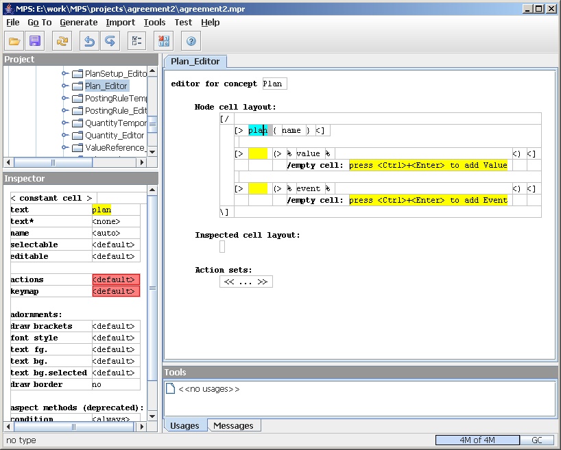
Figure 15: A constant for the word 'plan' in the plan line.
The constant is just the work plan. You can use constant
cells to place any markers or hints into an editor. You also use blank
constant cells to do layout such as blank lines and indentation. The
delimiters in the plan editor (such as [/ and
[>) are also constants defined in the editor for editors.
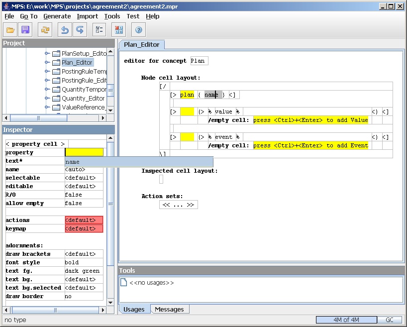
Figure 16: A property for the name in the plan line.
We show the name of the plan with a property cell. The property can be any property on the concept that the editor is defining for. Here I show I'm editing the property field on the inspector and I have a pop up showing all the properties on the plan concept - in this case there's only one.
The blank lines in the editor are simple constant cells. The value and event lines involve sub-editors. I'll skip over the values row and dig into the events.
The event row is a cell in the vertical cell collection
that is itself a horizontal cell collection with two
sub-cells: a blank constant cells and a ref node list cell
marked with (>.
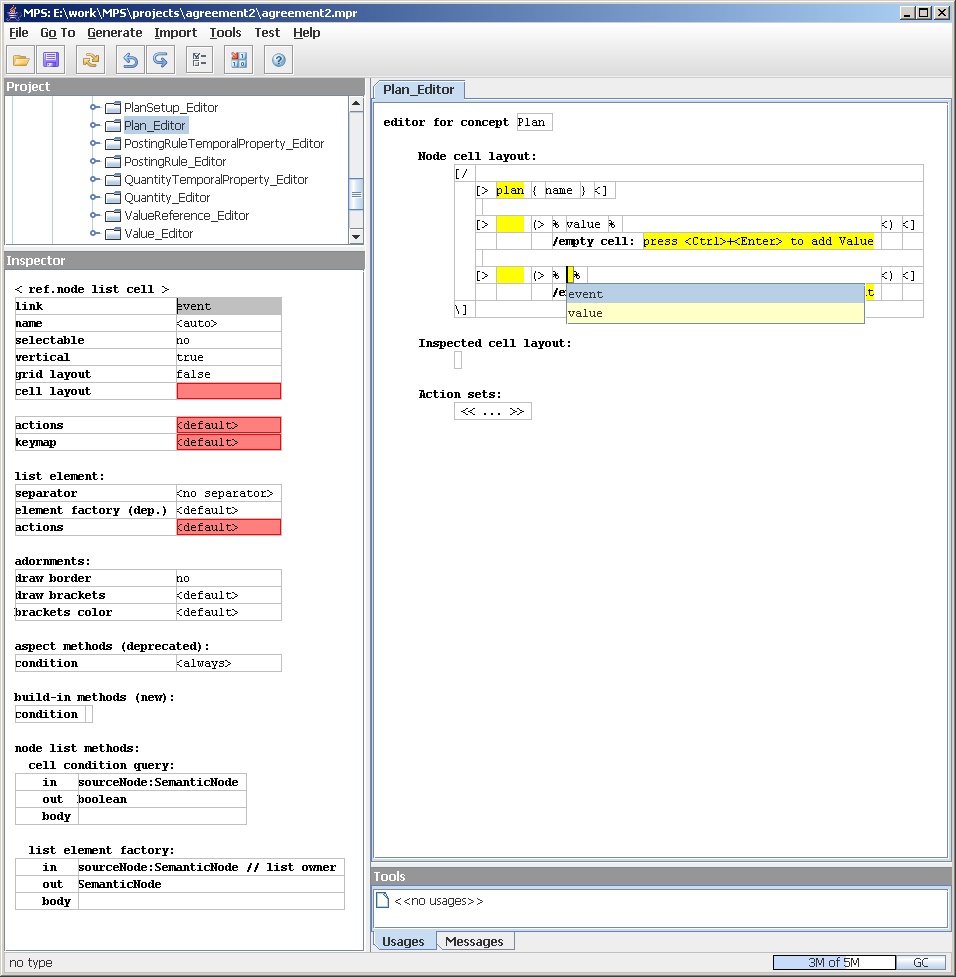
Figure 17: The link cell for events.
A link node has a rather more complex inspector than the
other nodes we've seen so far, but what interests us here is
two bits of information. As you might guess from the name, ref
node list cells will list elements based on following a link
in the schema. The editor tells which link to follow and that
the list should be made vertically. In Figure 17 I'm showing the pop
up for choosing the link (there actually is a choice this time)
in the editor pane itself. I could also do it in the
inspector. The editor pane shows the link name inside
% delimiters.
This little example suggests an interesting question when you define editors: should you edit using a separate inspector or directly in the editor pane itself? Keeping stuff out of the editor pane allows you to get an overall structure in the editor pane and to better the see the relationship between the editor definition and the resulting use of the editor. However if you put everything in inspectors you're constantly digging around to see what what's the the cells. This is part of the justification for terse markers (like the [/ and [>). You can click on the markers to see what they are in the inspector, but as you get used to that particular editor you get used to reading the editor pane directly. As you get used to it the terseness is helpful as it allows your eye to see more in less space.
You could also image multiple editors for different purposes, some to suit people's experience, others just to suit people's preferences. For example the intentional editor often allows you to switch quickly between different projections according to your preferences. When editing nested tables like this, you can choose to switch between nested tables (called boxy), a lisp like representation (lispy), or a tree view with properties (no cute name). To edit conditional logic there is a C-like programming language view, or a tabular representation. This quick switching between projections is useful because often you can see different aspects of a problem in different projections, so you can often understand more from easy changes between simple projections.
But let's get back to the example. We've seen that the plan editor has a cell that lists events vertically. How do we edit those events? At this point we switch over the event editor. Our final tool will embed these event editors in the plan editor.
Before we look at the editor, let's refresh ourselves on the schema for event.
Figure 6: Schema for Event
Here's the definition for the event editor, just using what's in the edit plane.

Figure 19: Editor pane definition for event editor.
If your eyes are getting use to the terse symbols, you should be able to get most of this without using the inspector. Essentially we have a vertical cell collection with two elements. The bottom of the two is a ref node list cell to list the posting rule temporal properties which will use the editor defined for that concept. The top cell however, shows some stuff we haven't seen yet.
The top cell is a horizontal cell collection. It has two sub-cells. The left sub-cell is a constant cell with the word 'event' - nothing new there. The new element is the second cell which is a ref node cell. Ref node cells are similar to ref node list cells, but are for cases where the referred to link is single valued - as it is here for the event type.
The ref node cell itself has two parts. The first indicates
which link to follow, in this case type. The
second indicates which property of the target to display. This
is an optional piece - had we left it out the event type would
render using its regular editor. Here we are indicating that
rather than do that, we just want to render a single property:
the name of the type.
Now lets look at the editor definition for posting rules. In the example plan (Figure 1, we see that the editor shows the effective date of the rule followed by the details of the rule itself. Here's the editor definition:
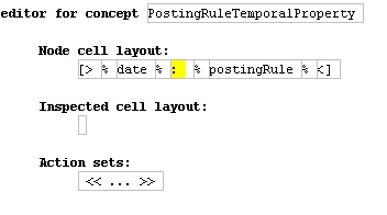
Figure 20: Editor for Posting Rule Temporal Property
This time the root cell is a horizontal cell collection with three sub-cells: a ref node cell for the date, a constant cell for the “:”, and another ref node cell for the posting rule itself. Both the date and posting rules are rendered with their own editor.
The last editor I'll show is the posting rule editor.
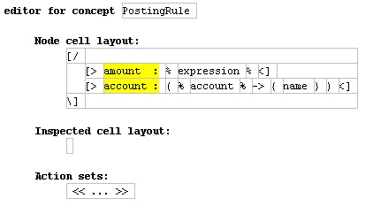
Figure 21: Editor for Posting Rule
Hopefully by now this is almost familiar. The root is a vertical cell collection with two horizontal cell collections as sub-cells. The top cell has the constant “amount:” and a ref node for the expression. The expression is rendered by the editor for expressions which is part of the formula language. The bottom cell has the constant “account:” followed by a ref node for the account which shows the name property of the account.
Describing an editor like this in text is awkward, at some point a screen cast of using the editor might be easier to follow. The editor editor is a bit awkward to get used to. This is partly because I'm not used to defining editors, partly its because more work is needed to make the editor editor usable. This is new territory so JetBrains is still learning how this kind of thing should work.
The important things to come out of this are that you need a lot of flexibility to define editors so they are as clean as the final plan editor turns out to be. To provide this flexibility you end up with a complex editor for editors. Although there's probably much that can be done to make these more usable, I suspect that it will still take some effort to define an editor that works well for a language. However since the editor is closely integrated with the other elements of a DSL, it's relatively easy to experiment and change editor definitions to explore the best editor.
The interplay here between the main edit window and the inspector reveals another point about editors for more complex DSLs such as an editor language. Rather than trying to get all your editing through a single projection, it's often best to use multiple projections that show different things. Here we see the overall structure of the editor in the main editor pane, and lots of details in the inspector. When designing the editor, you can move different elements between different panes.
In this case I can see that the third pane, showing the hierarchy of cells, would provide a useful third projection that would complement the inspector and wisiwigish main editor pane.
Defining the Generator
The last part of the trio is to write the generator. In this case we'll generate a java class that will create the appropriate objects using the framework we currently have. This plan builder class will create an instance of the service agreement class for each each plan we've defined using the DSL.
The code that we'll generate will look a little different to the java equivalent code we saw earlier. This is because of the way we're going to handle the calculation formulae. In the pure java version I used parameterized but limited formula classes to set the formulae. In this version the formulae are supplied by the formula language.
Here's the edit pane projection of the generator definition
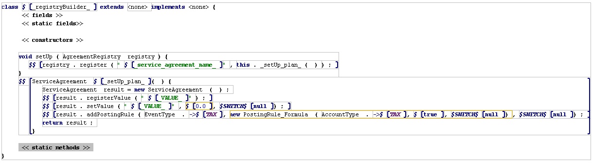
Figure 22: The definition for generation.
Here's the code it generates: (I've added some line breaks to help format it for the web page.)
package postingrules;

/*Generated by MPS*/


import postingrules.AgreementRegistry;
import postingrules.ServiceAgreement;
import postingrules.EventType;
import postingrules.AccountType;
import jetbrains.mps.formulaLanguage.api.MultiplyOperation;
import jetbrains.mps.formulaLanguage.api.DoubleConstant;
import jetbrains.mps.formulaLanguage.api.IfFunction;
import formulaAdapter.*;
import mf.*;

public class AgreementRegistryBuilder {
  public void setUp(AgreementRegistry registry) {
    registry.register("regular", this.setUpRegular());
    registry.register("lowPay", this.setUpLowPay());
  }
  public ServiceAgreement setUpRegular() {
    ServiceAgreement result = new ServiceAgreement();
    result.registerValue("BASE_RATE");
    result.setValue("BASE_RATE", 10.0, MfDate.PAST);
    result.setValue("BASE_RATE", 12.0, new MfDate(1999, 12, 1));
    result.addPostingRule(
      EventType.USAGE,
      new PostingRule_Formula(AccountType.BASE_USAGE, true,
        new MoneyAdapter(new MultiplyOperation(
          new ValueDouble("BASE_RATE"), new UsageDouble()),
          Currency.USD)),
      new MfDate(1999, 10, 1));
    result.addPostingRule(
      EventType.SERVICE_CALL,
      new PostingRule_Formula(AccountType.SERVICE, true,
        new MoneyAddOperation(
          new MoneyMultiplyOperation(new FeeMoney(), new DoubleConstant(0.5)),
          new MoneyConstant(10.0, Currency.USD))),
      new MfDate(1999, 10, 1));
    result.addPostingRule(
      EventType.SERVICE_CALL,
      new PostingRule_Formula(AccountType.SERVICE, true,
        new MoneyAddOperation(
          new MoneyMultiplyOperation(new FeeMoney(), new DoubleConstant(0.5)),
          new MoneyConstant(15.0, Currency.USD))),
      new MfDate(1999, 12, 1));
    result.addPostingRule(
      EventType.TAX,
      new PostingRule_Formula(AccountType.TAX, false,
        new MoneyMultiplyOperation(new FeeMoney(), new
        DoubleConstant(0.055))),
      new MfDate(1999, 10, 1));
    return result;
  }
  public ServiceAgreement setUpLowPay() {
    ServiceAgreement result = new ServiceAgreement();
    result.registerValue("BASE_RATE");
    result.registerValue("REDUCED_RATE");
    result.registerValue("CAP");
    result.setValue("BASE_RATE", 10.0, MfDate.PAST);
    result.setValue("REDUCED_RATE", 5.0, MfDate.PAST);
    result.setValue("CAP", new Quantity(50.0, Unit.KWH), MfDate.PAST);
    result.setValue("CAP", new Quantity(60.0, Unit.KWH), new MfDate(1999, 12, 1));
    result.addPostingRule(
      EventType.USAGE,
      new PostingRule_Formula(AccountType.BASE_USAGE, true,
        new IfFunction<Money>(
          new QuantityGreaterThenOperation(new UsageQuantity(), new ValueQuantity("CAP")),
          new MoneyAdapter(
            new MultiplyOperation(new ValueDouble("BASE_RATE"), new UsageDouble()),
            Currency.USD),
          new MoneyAdapter(
            new MultiplyOperation(new ValueDouble("REDUCED_RATE"), new
            UsageDouble()),
            Currency.USD))),
      new MfDate(1999, 10, 1));
    result.addPostingRule(
      EventType.SERVICE_CALL,
      new PostingRule_Formula(AccountType.SERVICE, true,
        new MoneyConstant(10.0, Currency.USD)),
      new MfDate(1999, 10, 1));
    result.addPostingRule(
      EventType.TAX,
      new PostingRule_Formula(AccountType.TAX, false,
        new MoneyMultiplyOperation(new FeeMoney(), new
        DoubleConstant(0.055))),
      new MfDate(1999, 10, 1));
    return result;
  }
}
As usual I'll pick some bits of the generation to walk through, without going into all of it. In particular the generated code from the formula is a rather ugly interpreter formula. This needs to be cleaned up and we hope to do that in the near future.
As with any template language, MPS's generator language allows you to write the class in template form with parameter references. One big difference with a language workbench is that you're using a projectional editor to define the template. So we can create a projectional editor for java class generation that knows about java syntax and uses this information to help you in your template generation. Here you see the generator editor has supplied markers for the various kinds of elements we see in java programs. This one only has methods so these others are unused.
MPS's generator language uses two kinds of parameter
references: property macros (marked with $) and
node macros ($$). Property macros interrogate the
abstract representation and return a string to be inserted
into the templated output. Node macros interrogate the
abstract representation and return further nodes for more
processing. Typically you'll use node macros to handle the
equivalent of loops in other templating systems.
Both types of macro are implemented by java methods in supporting java classes. In time the MPS team wants to replace java by a DSL that's designed to query the abstract syntax for generation, but for the moment they use java code.
The property macro is shown with references like
$[_registryBuilder_]. Selecting the $ allows you to see in the
inspector what java method is invoked by the macro.
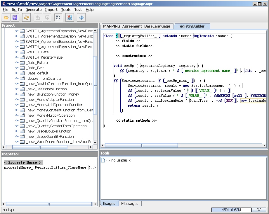
Figure 23: Linking to a java property macro
Integration between MPS and JetBrains's IntelliJ Java IDE allows me to hit the traditional IntelliJ <CTRL>-B and go the definition of the macro in Java
  public static String propertyMacro_RegistryBuilder_ClassName(SemanticNode sourceNode,
     SemanticNode templateNode, PropertyDeclaration property,
     ITemplateGenerator generator)
  {
    return NameUtil.capitalize(generator.getSourceModel().getName()) +
      “RegistryBuilder”;
  }
As you can see this is a pretty simple method. Essentially all it does is concatenate the name of the model that we're working on with “RegistryBuilder” to synthesize the class name.
This kind of thing allows you to synthesize various strings to insert in the generated code. While you're in the method you have access to various parts of the abstract representation: both of the agreement DSL and the generator DSL.
- sourceNode is the current node in the source language - in this case the agreement language.
- templateNode is the current node in the generator language, in this case the current node from the generator definition for builders
- property is the current property to which we're applying the macro
- property declaration is the declaration (from the schema) for this property.
- generator is the current generator instance - this links in with the current project and models.
You can see in the editor projection that this parameter
reference has a name in the editor projection:
_registryBuilder_. This is a label that allows
multiple references in the editor. You can see an example of
this later in the template. Each agreement is built with a separate method
(setUpRegular() and
setUpLowPay()). These need to be called from the
overall setup method. So the names of these methods have to be
referenced from both the method definition and the call. The
label _setUp_plan_ allows us to do that. In
Figure 22 you can
see the label both within the repeating lines of the setUp
method and as the method name in the template that's generated
for each method. Indeed, since the template editor
is a projectional editor, we can get pop menus to help us
choose these labels when we need them. Since the editor knows
we are building a template for a java program, it can use this
information to help us edit in the projection.
The second kind of macro we can see is a node macro. Node
macros appear in the editor as $$[more template
code]. The template code enclosed in the brackets is
applied to each node returned from the macro. Here's the
screen for the our agreement creation methods.
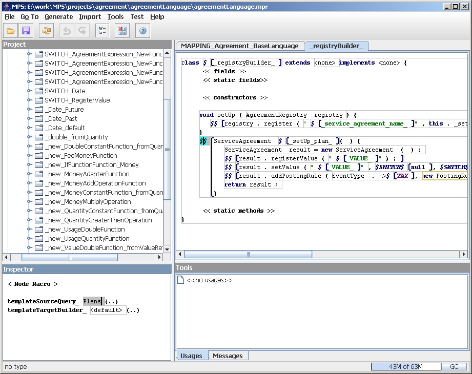
Figure 24: Linking to a node macro
This links to the following java code.
  public static List<SemanticNode> templateSourceQuery_Plans(SemanticNode parentSourceNode,
     ITemplateGenerator generator)
  {
    List<SemanticNode> list = new LinkedList<SemanticNode>();
    List<SemanticNode> roots = generator.getSourceModel().getRoots();
    for (SemanticNode node : roots) {
      if (node instanceof Plan) {
        list.add(node);
      }
    }
    return list;
  }
As you see, while a property macro returns a string, a node query returns a list of semantic nodes - in this case it walks through the roots of the abstract representation and returns all the plan nodes there. The generator will then generate the enclosed defined code for each plan. (In this way it acts rather like the looping directive in VTL).
When you're inside a node macro, the enclosed template is applied once for each node returned by the macro - setting the sourceNode argument to that node. So when we name the method later on we can use the following bit of java.
  public static String propertyMacro_Plan_SetUpMethod_Name(SemanticNode sourceNode,
      SemanticNode templateNode, PropertyDeclaration property,
      ITemplateGenerator generator)
  {
    Plan plan = (Plan) sourceNode;
    return "setUp" + plan.getName();
  }
Since the source node is a plan node, and the plan's schema has a name which is a string, we can just use the name to generate the name of the method.
The rest of the template works in essentially the same way. Either you obtain properties from your current source node, or you use a node macro to get another node to work on.
Defining template in MPS is really very similar to traditional template based approaches. Again we have an abstract representation that we query inserting the results in the generated code. The main difference visible from this example is that we are able to build projectional editors for different kinds of templated output - a java class in this case.
Summing Up
I hope this example gives you a feel of what it's like to use a language workbench - even if it's still somewhat of an embryo. In many ways this example is mostly lacking in the respect that it's still rather like a traditional textual DSL. As I suggested in language workbench, I think the really interesting DSLs will actually by quite different. But part of the the nature of this work is that we can't really see what they'll look like yet.
Significant Revisions
12 June 2005: First publication.